 |
| Motor and Case |
So, in the most recent lectures, we've talked a lot about what is called "
Design for Manufacturing and Assembly (DFMA)" -- or the combination of designing for the ease of manufacture and designing for the ease of assembly. Even the best assembly process in the world can fail under human errors like fatigue, time pressure, and plain carelessness. (We've all accidentally dived into an Ikea furniture assembly without fulling reading the instructions beforehand.) Hence, wisely, product designers tend to use 'mistake-proofing' features in order to make those kinds of careless mistakes obvious within seconds. Like a puzzle, either a piece fits or it doesn't. Otherwise, you'll end up with a deformed piece and an unclear final product. Honestly, those small DFMA pieces like a raised section of plastic can make or break how well-connected a handle is -- or even how easy it is to replicate the same level of quality that the company is promising with their product, over and over again. And, seeing that firsthand really fascinated me.
 |
| Exterior Case |
Example 1: Motor Casing
The case holding the motor has indentations/extrusions that act as a lock. The location and size of these markings ensure that the motor interfaces with the gearbox in a particular orientation -- and does not shift from that orientation.
Example 2: Exterior Casing
 |
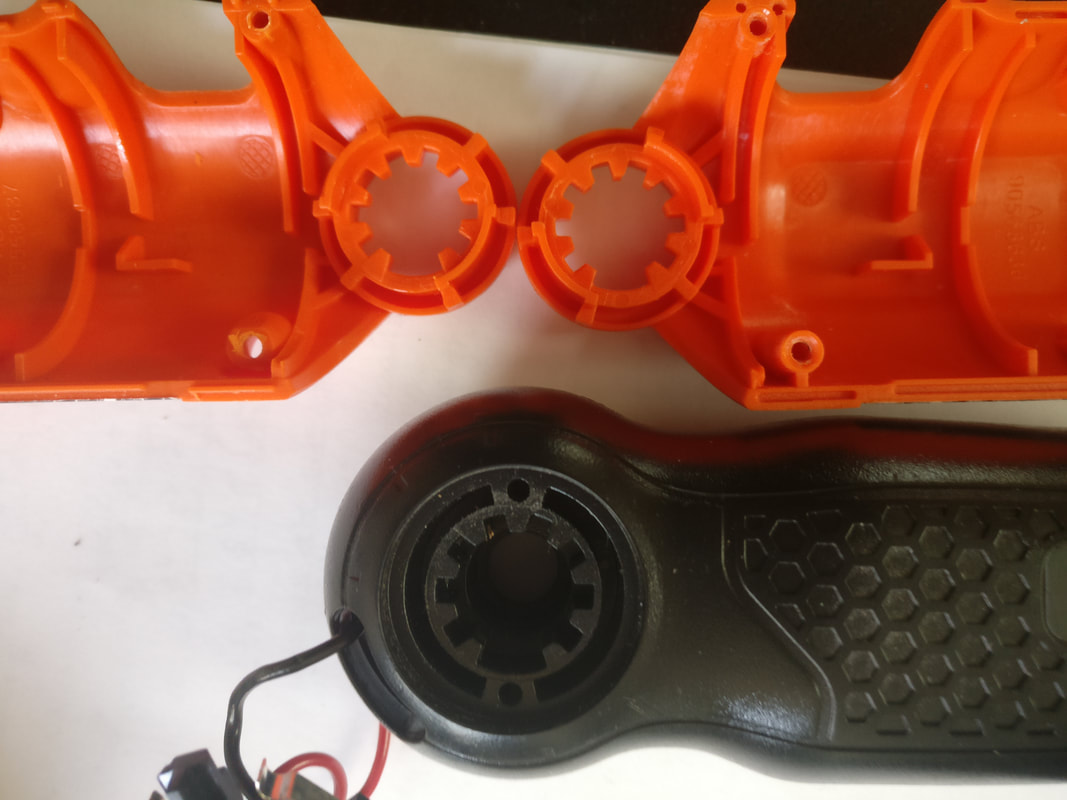
| Gear and Pin-Lock |
Similar to the motor casing, the exterior case that connects with the battery/handle also has extrusions that act as a lock. As seen with the image below, the orange, exterior case interconnects with the battery case and handle like a gear itself. The missing tooth, however, also adds another layer of security.
Example 3: Motor and Gear Pin
The driver is designed such that a u-shaped, metal pin locks the motor and gearbox in place (and in a specific orientation as determined by the motor casing).
Example 4: Handle Pivot Lock
 |
| Handle Lock |

The battery pack and handle connect with the exterior case of the motor and gearbox at a pivot connection. (See Example 2 above.) At this connection is a plastic screw with a spring. Users are able to push the top of this screw to lock and unlock the pivot motion due to how the screw is designed to interface with the exterior casing.


Comments
Post a Comment