Posts

Showing posts with the label Mechanics

Truss Design (Final)
Image
We finally made it to the end! After the preliminary design report, it was time to finalize our actual design (since we were given enough materials to make one truss to test). After doing a few more draft sketches and analysis, I was able to pick up on patterns on which types of designs produced the maximum strength (all within the parameters we were given). Finally, I came up with the sketch at the bottom-right, and the MATLAB analysis produced the highest load we were able to reach. We theorized that: two members would buckle first instead of just one (Members 3 and 4); the maximum load is 11.62 ± 0.063N; and the total cost of the truss is $290 (under the budget limit). From there, we moved to prototyping: we cut the straws as close as possible to the lengths specified in our final design. To create uniform gusset plates, our "joints," we used the circular cap of an individual Tropicana Orange Juice bottle. It met the area requirements and acted as a stamp...

CAD Final Project 03

Image
Planetary Carrier Somehow I was able to use Creo to create all of the components of the gearbox in one day (not recommended). After destructing the B&D Li2000, opening up the gearbox (which took a bit of strength), and calculating the measurements of each component, I was finally able to re-create all of the parts. Ring Gear Then, with each individual design, attach the components to one another in assembly (left) so that the kinematics or the motion of the CAD-assembled gear train resembled that in the gearbox. Planet Gear Additionally, I was able to use the motion analysis feature in Creo to model the pitch diameters and gear ratios for the cylinders representing each gear. (We did not go into depth on how to actually create the teeth on the gear since it requires manufacturing details we did not have.) Sun Gear Below is a video demonstrating the mechanism analysis for a multi-stage epicyclic gear train like the one used in the B&D Li2000 Screwdri...

CAD Final Project 02

Image
Motor and Case So, in the most recent lectures, we've talked a lot about what is called " Design for Manufacturing and  Assembly (DFMA) " -- or the combination of designing for the ease of manufacture and designing for the ease of assembly. Even the best assembly process in the world can fail under human errors like fatigue, time pressure, and plain carelessness. (We've all accidentally dived into an Ikea furniture assembly without fulling reading the instructions beforehand.) Hence, wisely, product designers tend to use 'mistake-proofing' features in order to make those kinds of careless mistakes obvious within seconds. Like a puzzle, either a piece fits or it doesn't. Otherwise, you'll end up with a deformed piece and an unclear final product. Honestly, those small DFMA pieces like a raised section of plastic can make or break how well-connected a handle is -- or even how easy it is to replicate the same level of quality that the company is promi...

CAD Final Project 01

Image
So ME359 has been great but it has been an exercise in stamina . For a 2-credit class, where weekly homework is 70% of your grade, this is a lot of time and energy -- but, still, exciting. Like I said before, I do really well when it comes to project-based learning and real-world applications. And this course's final project has really been wonderful for that. The final project is to reverse engineer the Black and Decker Li2000 Screwdriver and then use the computer-aided design (CAD) software Creo to re-create the gearbox. This is an interesting task since the B&D Li2000 uses a planetary gearbox, which consists of three types of a gears that all lie on the same horizontal axis. My task is to create the ring gear (the outermost gear), the three pinion gears that rotate around that inner radius of that ring, the sun ring around which the pinion gears rotate, and, then, the planetary gear connected to the central axis of the screwdriver. Ultimately, I need to create all of ...

Truss Design 02

Image
The second part of the final project for EK301 (Mechanics) consists of a preliminary design -- or, rather, several preliminary designs and one identified draft. Having the data from the straw lab test and the resultant code to determine the approximate load that a straw can hold based on its length, it took quite a bit of creativity to find the perfect combination of straws. However, to simplify this process, the class was instructed to use a MATLAB code that would take a design and then indicate which member of the truss would fail first. It is important to note that all designs were given the same parameters: Figure: One of two designs selected The truss must be a single, planar, simple truss.  Members must be joined concurrently at joints using the provided pins and double pinned to the guest plates.  Gusset plates may be any geometry but must have an area of less than 16 sq. cm. All joint-to-joint distances must be at least 10 cm and no longer than 16 cm. The ...

Truss Design 01

Image
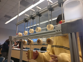
Testing Apparatus for Straw Lab Fall 2018 has been off to a very strong start. Being back in an academic environment is both really challenging and very inspiring. It has been tough to balance a full-time course load with a part-time job, but, so far, being able to still do classes like EK301 (Mechanics) has been rewarding. I missed creating designs and prototypes more -- much more -- than I realized. The truss design project that I just started has really switched on the engineering light bulb. I am not a huge fan of the traditional, exam-based learning that most engineering classes use, but these little peaks into applications and projects (which is how I fell in love with engineering) makes it all worthwhile. The final project started off with a lab test on the straws my group will use to design a sturdy bridge or 'truss.' The straw lab required lots of attention to detail and control, and, fortunately, I was able to stay later to complete the remaining tests and ...

Robot Art

Image
About a week or so ago, Professor Amy Banzaert - director of the  Wellesley Engineering Laboratory  - sent out an invite to enter an international competition and several students (we) answered the call. We're building a robot to make art! The  2016 1st Annual International RobotArt Competition  aims to foster innovation in artificial intelligence, processing and robotics. Considering that Wellesley is  not  an engineering school (and doesn't have an engineering department), we definitely have our work cut out for us and must be resourceful in our project. We had our first meeting on the Sunday before March and covered quite a bit for an intro into the area: What is robotics?  Have robots been built for painting, decorating, etc? What are our backgrounds?  How can we divide the project into parts? What to do for next time? With all of those questions in mind, we are absolutely seeking to grab more teammates and seek out help in ar...

CAKEBOT: "Demo Day is Coming" II

Image
Demo Day is Thursday, December 18 -- but our project website  was due  Monday, December 15. Having met several times over the last week and half, my team has been pushing to finally finish our full mechanism. Griffin and I were lucky to have the electronics systems finished, except for the limiting switches, a few days ago. I tested the motors and Arduino code to ensure that we were able to move them appropriately, and Griffin worked diligently to wrap up the GUI as I tried to offer what little python I remembered. However, in the midst of finals week at both Olin and Wellesley, the mechanical aspects fell a  little behind as my teammates were fighting for space in the woodshop and laser cutter with the many other Olin students who needed it for their own projects. With the majority of my project finished, I took charge over the website as the only individual familiar with Weebly hosting-site. Originally, Griffin setup an HTML template for us all to edit but, as it ...

CAKEBOT: Sprint Review II

Image
Leading up to the second Design Review, CakeBot team attacked our project with a vengeance, ordering supplies for the frosting dispenser asap and building the frame for it, searching for new motors and drivers to build the actuators for nozzle and platform movement. Cassie and Emily, once the orders came in, worked on modifying the Wilton Decorator Pro to attach to a DC motor for up-and-down movement, i.e. pressure on the frosting container. Another stepper motor, compatible with the Adafruit Motorshield, was ordered and integrated by using a belt to move the nozzle/dispenser across the radius of the cake. Griffin and I also ordered a separate stepper driver from Pololu  to drive the Rotating Platform's "high-current" stepper motor. In testing our apparatus, with a finally-mounted Decorator Pro, we were able to observe three mechanisms: Extruding the frosting to create a border: The DC motor moves the plunger downwards at a constant rate while the platform rot...

CAKEBOT: Stepper Motor Issues

Image
 After our insightful meeting on Sunday, the CAKEBOT team dived into some hard science. Specifically, Griffin and I (the Sensors/Software sub-team) looked into having the platform rotate -- rather than trying to rotate the platform by hand or change the position of the frosting nozzle. To do so, we looked into using a stepper motor (360-deg versus a 120-deg Servo motor) and using the Adafruit Arduino Motorshield from a previous lab. Coding-wise, I used the sample Adafruit code to test out the four types of motor-turns : single coil, double coil, interleave, and microstep.  Double coil allows for greater torque while microstep allows for smooth, continuous turns or "steps." Interleave alternates between single and double coil for stepping. The code worked beautifully, but we painfully discovered that the motor we were using was drawing more current than the Adafruit Motorshield could supply, causing quite a bit of smoking on the chips. We sought the advice of Siddhartan and ...

CAKEBOT: Team Meeting I

Image
At our team meeting on Sunday after the first spring review, the crew decided to become familiar with the field at hand. We baked and decorated a 9-inch cake for observation. Baking the cake did take a portion of time and for the majority of that time, the team discussed ways in which we could extrude frosting. Emily and Cassie had taken a field trip to a Baking Store and found a Wilton Decorator Pro, which consisted of a plunging mechanism to extrude frosting from the attached storage container. Additionally, the tool allowed for interchangeable tips to create circles, stars, and waves. We took such a luxury into account for our design too. We reversed-engineered the Decorator Pro to understand how we could ensure that the frosting was forced out at a constant pressure. The Mechanics sub-team (Cassie and Emily) discussed how to remove the springs in order to directly integrate the equipment into the CAKEBOT, attaching the plunging arm to a motor for vertical movement. By then, the...

CAKEBOT: Sprint Review I

Image
At the end of every two weeks, there is a "sprint review" where professors circulate between groups to hear about and give feedback on the progress of each team project. The CAKEBOT team met for a long session the night before to finalize the physical, first iteration of the CakeBot design. We also sketched out the integration of the components for future sprints  to demonstrate that we at least thought about the mechanical, electronic and software pieces. The actual prototype itself focused on the cake rotating platform -- which we knew we would absolutely need for decorations on the side/walls of a cake -- and initial ideas on the icing dispensing system for the face. For the rotating platform, I used a cut-out circle of 9-inch diameter (for standard cake size) and we connected it to a servo motor. I then programmed the Arduino to "sweep" the servo to and fro; the motor itself was pushed into a hole cut out in the foam base. The foam base most likely will be a w...

PoE: Lab 3 -- PID Control RESULTS

Image
Using the CoolTerm program to read Arduino serial values to a txt file, we print the serial output values of position, target position, error, and motor output and then used MATLAB to plot these values.We used the PID equation, output = Kp*Error + Ki*Total + Kd*Difference , where Error = target ­ count,  Total = total + error, and Difference = Error_previous - Error_current. With a little experimentation, we found that our control works best when Kp = 14, Ki = .01, and Kd = .1. Yet, we noticed that the accuracy of our plots was not as high as it could be with a 36­resolution encoder, which caused large steps in our plots, as seen in Figures 4 and 5. We tried increasing the accuracy by using different encoders, up to 72­resolution. Challenges: A key challenge in this lab was understanding the dynamics of PID control system and how to translate them into the encoder­motor system we built. Another challenge we had to overcome was dissecting th...

PoE: Lab 3 -- PID Control

Image
Objectives Use an analog IR reflective sensor to measure the angular position of a motor shaft. Create a closed-loop controller for a brushed DC motor with your DIY shaft encoder. Characterize and visualize the performance of your closed-loop motor controller. In this lab, we used an analog infrared reflective sensor to build an encoder to measure the position of the shaft of a DC motor. With the sensor, the more IR light that is reflected back to the phototransistor, the closer Vout will be to zero (see schematic). We used the position reported by the encoder as a signal around which to design a feedback loop that ensures your motor will go to any position you command it to (even under load). After setting up the sensor circuit with the Arduino, we began to build the encoder. An encoder is a circle with distinct patterns of black and white shapes, usually triangles, that signify on-off or high-low. We placed our 36-resolution*, carboard encoder right on the shaft...

Catch-up and the CAKEBOT: Final PoE Project

Image
Hello again!  It has been a while since my last descriptive post about my engineering journey though a lot has happened over the past few weeks, from PoE to We-Lab to W.E.S. to research talks. I almost have no time to blog -- almost no time ... So, to get back on track with my documenting the experience, I am submitting a series of posts about all the new developments. Olin's Principles of Engineering (PoE) PoE has kept me extremely busy as the labs have become more and more challenging, moving from simple LED lights to a 3D scanner to Proportional-Integral-Derivative (PID) motor control. PoE is meant to give students a balanced background in both electronics, mechanics and programming -- in preparation for the final project. For the final project, students were allowed to form their own teams and project ideas, which created a frenzy throughout the classroom. People heckled and raced to find a spot on highly-coveted ideas or urge others to join them in an idea with littl...

Final Report of Lab 2

Image
In this lab, we embarked on the journey of creating a 3D­scanner utilizing two Hobbying servo motors, a Sharp Infrared Distance Sensor, and an Arduino Uno. We created a connector that would allow us to secure a reliable connection between our Arduino and IR sensor. We patiently assembled the connector by crimping three JST connectors onto appropriately stripped wires to fit into a 3­pin JST connector. We tested the functionality of the primary parts: the sensor, the Arduino, and the servos. We adjusted and ran the AnalogInput example from the Arduino example library, which caused our sensor to blink at an increased rate whenever an object was nearby. Similarly, we ran AnalogOutSerial from the Arduino library, which allowed us to verify that values were being transmitted and that they consistently changed when an object was nearby. Lastly, we made sure our servos worked and could be controlled, using the "Sweep” example to rotate the servos. After confirming the functionality o...

PoE: Second Day of Lab 2

Image
Second day of Lab 2 and the lab deadline has been extended to the next class period! Plenty of time to work out the kinks and whatnot of the project... Though, this is a step up from Lab 1. Following from last post's updates, we have sent the pan-tilt design to the Wellesley machinist (Larry Knowles) for his advice on what materials to use and how to construct it. Hopefully, he'll be available next week and we can finish it on Monday. Furthermore, I've use the resources I found to begin writing the code for both the infrared sensor, calibration of the sensor values and MATLAB translation (visualization). The YouTube video below is an in-depth tutorial of how to use a infrared sensor and real-time draw its data into a MATLAB axis. The connector for the sensor has been developed and, when the pan-tilt mechanism and the foam object is constructed, we can begin testing the code. I am eager to see how these servo motors work. I feel that I'll be seeing more of them in ...