Posts

Showing posts with the label Short-term

New Year!

Image
Wow... it's already the end of December and New Year's Day is right around the corner. I'm thankful for a lot this year: I was able to travel again, help people learn about design and their own potential, develop more skills, discover more about myself.... and, despite numerous challenges and some disappointments, I'm still pushing forward. I know I neglected this blog during the fall semester. (Sorry.) However, I hope to pick things up again in the spring. I'm coming up on my final and last semester in college -- which sounds just as crazy to me as it probably does to you. **Recap**  I did finish my report,  An overview of economic theory and approaches for evaluating the productivity of water on Santiago Island in Cape Verde, from this summer with INIDA. Hopefully, I can publish out-of-house too. Also, I presented at the 2017 Tanner Conference on my activities in Cape Verde this summer, and it seems that a number of people liked my brief talk. Then, this fall...

WP: Farmer Interviews 02

Image
The second day of interviews was definitely the best! Although many spouted their opinions to us on farmers using traditional irrigation (instead of gota-gota/drip irrigation), it was absolutely amazing to see it in action/finally understand the system and talk to the farmers directly on why they have stuck with traditional systems. We got different opinions and I absolutely want to hear more from that target: We also spoke with two more gota-gota farmers. One is the only member of farmers' association using gota-gota; The other owns a private - and exporting - company. (Note:  Again, all of these farmers are allowing us to use photos and names. ) First things first, traditional irrigation is referred to as " alargamento ," and you really won't understand it unless you see it. This technique is ancient ("since Adam and Eve" as one farmer said) and, generally, farmers learn it from their fathers. We were so lucky to see it in action, because, when you...

Robot Art

Image
About a week or so ago, Professor Amy Banzaert - director of the  Wellesley Engineering Laboratory  - sent out an invite to enter an international competition and several students (we) answered the call. We're building a robot to make art! The  2016 1st Annual International RobotArt Competition  aims to foster innovation in artificial intelligence, processing and robotics. Considering that Wellesley is  not  an engineering school (and doesn't have an engineering department), we definitely have our work cut out for us and must be resourceful in our project. We had our first meeting on the Sunday before March and covered quite a bit for an intro into the area: What is robotics?  Have robots been built for painting, decorating, etc? What are our backgrounds?  How can we divide the project into parts? What to do for next time? With all of those questions in mind, we are absolutely seeking to grab more teammates and seek out help in ar...

PHYS250H: Power Supply Project II

Image
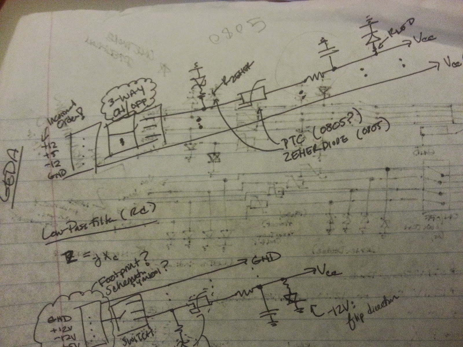
The printed circuit board design is a projection of the schematic design. The placement of the footprints for the set of jumpers was positioned intentionally to allow for the power lines to be connected simultaneously as well as for easy access when soldering. We went through several iterations in design due to mishaps in communication -- a key issue in engineering firms. It took me a little while to understand just exactly how Battat envisioned this project and the best way to design such. At first, different components were in place than in the final design: I moved from three-way jumpers that resembled the slapstick original design for the Electronics Lab (without direct input into the rails); to long rectangular flow mirroring the circuit schematic; and to a dual-pin jumper and stacked 805 footprints. Finally, I ended with a reasonable and compact design for the PCB power supply. OSH Park, a community printed circuit board order, charges $5 per square inch of a dual-layer bo...

PHYS250H: Power Supply Project I

Image
For Fall 2014, I decided to continue my work under Professor James Battat with the dark matter detector and he suggested doing so under PHYS250H -- an independent study in the Physics Department -- in order to receive credit for it. However, the project portion of the course veered from work with the PCB I created earlier and towards design of a PCB power supply for his Spring class PHYS310 "Experimental Physics." The power supply was needed for an Electronics student lab,  where a five-pin DIN draws in four voltage levels of +12V, -12V, +5V and GND for a solderless breadboard. The PCB I designed would use this connector to draw in the four voltage levels, filter for overcurrent and allow direct input into the rails of a solderless breadboard. At the beginning of the process, Battat and I create a concept diagram demonstrating the overall flow of the power supply and, from it, a rough circuit diagram was generated. Over time, the schematic changed with additional and...

CAKEBOT: Design Review II

Image
This design review went very well for CAKEBOT. We took the feedback from our last review and tried to apply the criticisms and encouragement we received to this sprint. We were able to demonstrate a proper integration of the electronics, software and mechanics. Griffin updated the GUI for more tip changes, "Confirmation" dialogue boxes, and on-screen drawing. While he was out at You-Do-It, he brought me 2 limit switches for calibration and I also requested some safety switches, i.e. a master on-off switch and a confirmation (or "pause") button -- all to be mounted afterwards. Below is the presentation with updated goals and videos of the demonstration. (The form is now closed but we received great feedback).

PoE: Lab 3 -- PID Control RESULTS

Image
Using the CoolTerm program to read Arduino serial values to a txt file, we print the serial output values of position, target position, error, and motor output and then used MATLAB to plot these values.We used the PID equation, output = Kp*Error + Ki*Total + Kd*Difference , where Error = target ­ count,  Total = total + error, and Difference = Error_previous - Error_current. With a little experimentation, we found that our control works best when Kp = 14, Ki = .01, and Kd = .1. Yet, we noticed that the accuracy of our plots was not as high as it could be with a 36­resolution encoder, which caused large steps in our plots, as seen in Figures 4 and 5. We tried increasing the accuracy by using different encoders, up to 72­resolution. Challenges: A key challenge in this lab was understanding the dynamics of PID control system and how to translate them into the encoder­motor system we built. Another challenge we had to overcome was dissecting th...

PoE: Lab 3 -- PID Control

Image
Objectives Use an analog IR reflective sensor to measure the angular position of a motor shaft. Create a closed-loop controller for a brushed DC motor with your DIY shaft encoder. Characterize and visualize the performance of your closed-loop motor controller. In this lab, we used an analog infrared reflective sensor to build an encoder to measure the position of the shaft of a DC motor. With the sensor, the more IR light that is reflected back to the phototransistor, the closer Vout will be to zero (see schematic). We used the position reported by the encoder as a signal around which to design a feedback loop that ensures your motor will go to any position you command it to (even under load). After setting up the sensor circuit with the Arduino, we began to build the encoder. An encoder is a circle with distinct patterns of black and white shapes, usually triangles, that signify on-off or high-low. We placed our 36-resolution*, carboard encoder right on the shaft...

Final Report of Lab 2

Image
In this lab, we embarked on the journey of creating a 3D­scanner utilizing two Hobbying servo motors, a Sharp Infrared Distance Sensor, and an Arduino Uno. We created a connector that would allow us to secure a reliable connection between our Arduino and IR sensor. We patiently assembled the connector by crimping three JST connectors onto appropriately stripped wires to fit into a 3­pin JST connector. We tested the functionality of the primary parts: the sensor, the Arduino, and the servos. We adjusted and ran the AnalogInput example from the Arduino example library, which caused our sensor to blink at an increased rate whenever an object was nearby. Similarly, we ran AnalogOutSerial from the Arduino library, which allowed us to verify that values were being transmitted and that they consistently changed when an object was nearby. Lastly, we made sure our servos worked and could be controlled, using the "Sweep” example to rotate the servos. After confirming the functionality o...

PoE: Second Day of Lab 2

Image
Second day of Lab 2 and the lab deadline has been extended to the next class period! Plenty of time to work out the kinks and whatnot of the project... Though, this is a step up from Lab 1. Following from last post's updates, we have sent the pan-tilt design to the Wellesley machinist (Larry Knowles) for his advice on what materials to use and how to construct it. Hopefully, he'll be available next week and we can finish it on Monday. Furthermore, I've use the resources I found to begin writing the code for both the infrared sensor, calibration of the sensor values and MATLAB translation (visualization). The YouTube video below is an in-depth tutorial of how to use a infrared sensor and real-time draw its data into a MATLAB axis. The connector for the sensor has been developed and, when the pan-tilt mechanism and the foam object is constructed, we can begin testing the code. I am eager to see how these servo motors work. I feel that I'll be seeing more of them in ...

PoE: Beginning Lab 2

Image
We're Making a 3D Scanner! I don't know how we jumped from flashing LEDs to this project, but I have managed to be both excited and scared. Lab 2 requires us to rely quite a bit on our mechanics knowledge to design and build a pan-tilt project with two servo motors and an infrared sensor. Together, the mechanical object will collect dimensions of a foam-based letter and, then, use MATLAB to draw the 3D representation of the object. I have never worked with servo motors before but I have worked with MATLAB and sensor data. Again, with my partner Ashley, we will ensure that we do not fall behind on this project like the last one. (Plus, I am eager to see what I can do!) We already have a few ideas to pursue as well as a few concerns. Pan-tilt projects are relatively simple to design but building them is another story. I am not a MechE (mechanical engineer) and neither is my partner. However, we are both trained in the machine shop and can use our Wellesley resources to ...

PoE: Finishing Lab 1

Image
After we resolved the minuscule problems affecting our progress on the lab, Ashley and I worked diligently to catch up and even worked over the weekend for a long period to complete both parts of the code. Part I: Four Modes with a Single Button We had designed the operations of the four modes to be switched between but we were still figuring out the "switching" mechanism on the Saturday before the due date. Many of the examples we had seen were too elaborate and we wanted a simple solution. We found one by using millis() , a pushCounter and debounce operations. Millis() is a way to keep track of time, without stopping the entire program (i.e. delay), and we can use it for comparisons between the current timespan and a set interval to form different flashstates. On the other hand, a "button state change detection" tutorial showed us how to count presses of a button and cycle through four states. However, many times the Arduino will read several button presses ...

PoE: Working on Lab 1

Image
For the second class of "Principles of Engineering," my partner and I began where we left off last class -- just beginning the second lab. Consisting of two parts, Lab 1 focuses on ensuring the students attain a certain level of familiarity with the ArduinoUNO's coding language and applying the board in an electrical circuit. Specifically, the first part asks us to generate a code where three LEDs experience four sets of light patterns with the use of a single button. My partner and I started off well: we wrote out what we wanted the code to do; broke the procedure into steps (stages); and sketched a draft of how to structure these stages -- coding-wise. We wrote out the entire code to, at least, try something out. We uploaded the code -- and nothing. And, so, the troubleshooting began. Simplifying the code and removing the last two stages to test out the "switching" mechanism did not have an effect. Removing the second stage did not have an effect....

The Very Last Week

Image
It's Wednesday, July 30th and that means I have less than 6 hours to fully prepare for my poster presentation tomorrow (and pack). This entire week I have fluctuated between PCB layout design in gEDA software and finalizing the internship, though I have made the personal decision to continue my involvement beyond this summer. This entire week has been very active and I barely have time to come up for air. Over the last few days, I have submitted several renditions of the PCB layout, resolving issues such as incorrect traces, lost files, placing components on a dual-sided PCB and more. Most Physics and EE students -- including my advisor -- do/did not design a PCB until graduate school. And, here I am, as a rising sophomore, creating my own PCB. As I mentioned before, this internship has given me more skills than I could possibly imagine. Updates: MUXs are placed on the back-side of the board and connected to the top components with "vias" Two distinct ground planes...

Making Headway on the PCB

Image
We're finally making headway on this project! We are very close to finishing the PCB (thanks to a few extra weekend work days) and could most likely finish the PCB layout tomorrow. After passing around several versions of pieces of the PCB board, using the gschem software, Dr. Phillips, Prof. Battat and I have redrawn electrical connections, replaced components with others, implemented PCB footprints in all the components, checked for back termination and proper voltage levels, and, overall, used the "divide and conquer" method. I started with a tutorial on gEDA schematic drawings, and, now, I am drawing complicated, detailed schematics on my own. Most first-year Engineering majors wouldn't have half as much exposure to such professional techniques as Dr. Phillips and Prof. Battat have allowed me. They're absolutely challenging me, but I wouldn't take back one minute of this experience. Over the last two days, I've received constant feedback from my ad...

Hitting a Speed Bump

Image
With all the progress made last week with the counter, we still are having trouble seeing the correct Vout signal pattern of the MUX. Prof. Battat returned today and looked at the setup himself, and we made a few changes. Today was filled with lots of bumps and hills, and, at one point, we even thought we had burned out the counter and solder another just in case. In the book Moonwalking with Einstein , Foer states that humans sometimes reach a "plateau" where their progress or betterment at a task no longer increases. Nonetheless, he finishes by writing that one can overcome this stage by being extra-meticulous in their search for error. With 3 weeks left, it is time to be extra diligent in our work. The first change was to remove the 50 Ohm surface-mount, resistors on the MUX because it was affecting the counter's ability to count. Dr. Phillips and I were unsure how to address the issue earlier, but he suggested the use of buffers. The binary counter can drive 50 mA...