Posts

Showing posts with the label Circuitry

Robot Art

Image
About a week or so ago, Professor Amy Banzaert - director of the  Wellesley Engineering Laboratory  - sent out an invite to enter an international competition and several students (we) answered the call. We're building a robot to make art! The  2016 1st Annual International RobotArt Competition  aims to foster innovation in artificial intelligence, processing and robotics. Considering that Wellesley is  not  an engineering school (and doesn't have an engineering department), we definitely have our work cut out for us and must be resourceful in our project. We had our first meeting on the Sunday before March and covered quite a bit for an intro into the area: What is robotics?  Have robots been built for painting, decorating, etc? What are our backgrounds?  How can we divide the project into parts? What to do for next time? With all of those questions in mind, we are absolutely seeking to grab more teammates and seek out help in ar...

2015 MIT Lincoln Laboratory

Image
This summer, I have been given the great opportunity to join the internship program at MIT Lincoln Laboratory in their Cybersecurity division. Unfortunately, because of the level of security, I cannot discuss my work - and thus the lack of blog posts this summer. However, I have only a week left of the internship program and time has flown by so fast. This summer has absolutely been incredible and I would not trade it for anything. From the facility tours to my summer work to the monthly lunches with Wellesley alums working there, I believe I really explored myself as an engineer  and an economist. While engaging in the culture at the Laboratory, I was forced to reflect on what type of environment I want to work in - academia, government, FFRDC or private sector - and, frankly, I still am not sure as I have no comparison for the private sector outside of a few tours. Regardless, this summer has greatly increased the number of things I need to consider for the field I will choose...

PHYS250H: Power Supply Project II

Image
The printed circuit board design is a projection of the schematic design. The placement of the footprints for the set of jumpers was positioned intentionally to allow for the power lines to be connected simultaneously as well as for easy access when soldering. We went through several iterations in design due to mishaps in communication -- a key issue in engineering firms. It took me a little while to understand just exactly how Battat envisioned this project and the best way to design such. At first, different components were in place than in the final design: I moved from three-way jumpers that resembled the slapstick original design for the Electronics Lab (without direct input into the rails); to long rectangular flow mirroring the circuit schematic; and to a dual-pin jumper and stacked 805 footprints. Finally, I ended with a reasonable and compact design for the PCB power supply. OSH Park, a community printed circuit board order, charges $5 per square inch of a dual-layer bo...

PHYS250H: Power Supply Project I

Image
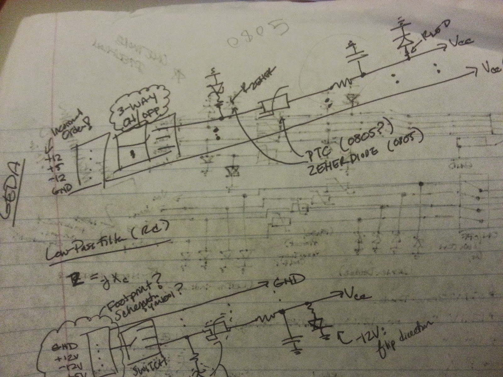
For Fall 2014, I decided to continue my work under Professor James Battat with the dark matter detector and he suggested doing so under PHYS250H -- an independent study in the Physics Department -- in order to receive credit for it. However, the project portion of the course veered from work with the PCB I created earlier and towards design of a PCB power supply for his Spring class PHYS310 "Experimental Physics." The power supply was needed for an Electronics student lab,  where a five-pin DIN draws in four voltage levels of +12V, -12V, +5V and GND for a solderless breadboard. The PCB I designed would use this connector to draw in the four voltage levels, filter for overcurrent and allow direct input into the rails of a solderless breadboard. At the beginning of the process, Battat and I create a concept diagram demonstrating the overall flow of the power supply and, from it, a rough circuit diagram was generated. Over time, the schematic changed with additional and...

CAKEBOT: Demo Day

Image
Demo Day was a huge success!  The night before, Griffin and I were able to see the final product and discuss what to work on/test for a brief moment, and I was able to get there before the scheduled presentation to clean up a previous team's remnants and prep our own product. Griffin and I were able to test a spiral design on a few sheets of paper on top of our dummy cake -- and it looked beautiful as onlookers watched and Griffin videotaped a portion. Unfortunately, we were unable to setup the limit switches properly as I would have liked to do so. Though, the positioning system of our polar-coordinate-based rotating platform worked so well that it did not matter as much as I was worried it would. Cassie and Emily then walked in with our final, pre-frosted chocolate cake for the demonstration. While they went on to watch others demonstration, I decided to create and edit a short promo/trailer video of our Cakebot to add into the presentation that would happen in 15 minutes. ...

CAKEBOT: "Demo Day is Coming" I

Image
After the DRII, we took our compliments and criticism to heart and set off to finish what we said we would do before the final Demo Day. Griffin and I looked into the malfunctioning rotating platform and realized the issue was more mechanical than anything electrical or software: Cassie and Emily made note to handle the issue in our final prototype. Griffin and I worked heavily on integrating the pyserial code with the Arduino system: he came up with the genius idea of having the pyserial/GUI send three-letter codes that correspond with motor actions, i.e. calibration of the platform stepper, forward movement of the top stepper, extruding of the top DC, extruding of the side DC motor. We were able to record all our changes of the final sprint code using  GitHub  -- a cloud management system for sharing and collaborating on code. Griffin introduced me to the system and I plan on using it much more often now that I understand its magic. Furthermore, in testing all the m...

CAKEBOT: Sprint Review II

Image
Leading up to the second Design Review, CakeBot team attacked our project with a vengeance, ordering supplies for the frosting dispenser asap and building the frame for it, searching for new motors and drivers to build the actuators for nozzle and platform movement. Cassie and Emily, once the orders came in, worked on modifying the Wilton Decorator Pro to attach to a DC motor for up-and-down movement, i.e. pressure on the frosting container. Another stepper motor, compatible with the Adafruit Motorshield, was ordered and integrated by using a belt to move the nozzle/dispenser across the radius of the cake. Griffin and I also ordered a separate stepper driver from Pololu  to drive the Rotating Platform's "high-current" stepper motor. In testing our apparatus, with a finally-mounted Decorator Pro, we were able to observe three mechanisms: Extruding the frosting to create a border: The DC motor moves the plunger downwards at a constant rate while the platform rot...

CAKEBOT: Stepper Motor Issues

Image
 After our insightful meeting on Sunday, the CAKEBOT team dived into some hard science. Specifically, Griffin and I (the Sensors/Software sub-team) looked into having the platform rotate -- rather than trying to rotate the platform by hand or change the position of the frosting nozzle. To do so, we looked into using a stepper motor (360-deg versus a 120-deg Servo motor) and using the Adafruit Arduino Motorshield from a previous lab. Coding-wise, I used the sample Adafruit code to test out the four types of motor-turns : single coil, double coil, interleave, and microstep.  Double coil allows for greater torque while microstep allows for smooth, continuous turns or "steps." Interleave alternates between single and double coil for stepping. The code worked beautifully, but we painfully discovered that the motor we were using was drawing more current than the Adafruit Motorshield could supply, causing quite a bit of smoking on the chips. We sought the advice of Siddhartan and ...

CAKEBOT: Sprint Review I

Image
At the end of every two weeks, there is a "sprint review" where professors circulate between groups to hear about and give feedback on the progress of each team project. The CAKEBOT team met for a long session the night before to finalize the physical, first iteration of the CakeBot design. We also sketched out the integration of the components for future sprints  to demonstrate that we at least thought about the mechanical, electronic and software pieces. The actual prototype itself focused on the cake rotating platform -- which we knew we would absolutely need for decorations on the side/walls of a cake -- and initial ideas on the icing dispensing system for the face. For the rotating platform, I used a cut-out circle of 9-inch diameter (for standard cake size) and we connected it to a servo motor. I then programmed the Arduino to "sweep" the servo to and fro; the motor itself was pushed into a hole cut out in the foam base. The foam base most likely will be a w...

PoE: Lab 3 -- PID Control RESULTS

Image
Using the CoolTerm program to read Arduino serial values to a txt file, we print the serial output values of position, target position, error, and motor output and then used MATLAB to plot these values.We used the PID equation, output = Kp*Error + Ki*Total + Kd*Difference , where Error = target ­ count,  Total = total + error, and Difference = Error_previous - Error_current. With a little experimentation, we found that our control works best when Kp = 14, Ki = .01, and Kd = .1. Yet, we noticed that the accuracy of our plots was not as high as it could be with a 36­resolution encoder, which caused large steps in our plots, as seen in Figures 4 and 5. We tried increasing the accuracy by using different encoders, up to 72­resolution. Challenges: A key challenge in this lab was understanding the dynamics of PID control system and how to translate them into the encoder­motor system we built. Another challenge we had to overcome was dissecting th...

PoE: Lab 3 -- PID Control

Image
Objectives Use an analog IR reflective sensor to measure the angular position of a motor shaft. Create a closed-loop controller for a brushed DC motor with your DIY shaft encoder. Characterize and visualize the performance of your closed-loop motor controller. In this lab, we used an analog infrared reflective sensor to build an encoder to measure the position of the shaft of a DC motor. With the sensor, the more IR light that is reflected back to the phototransistor, the closer Vout will be to zero (see schematic). We used the position reported by the encoder as a signal around which to design a feedback loop that ensures your motor will go to any position you command it to (even under load). After setting up the sensor circuit with the Arduino, we began to build the encoder. An encoder is a circle with distinct patterns of black and white shapes, usually triangles, that signify on-off or high-low. We placed our 36-resolution*, carboard encoder right on the shaft...

Catch-up and the CAKEBOT: Final PoE Project

Image
Hello again!  It has been a while since my last descriptive post about my engineering journey though a lot has happened over the past few weeks, from PoE to We-Lab to W.E.S. to research talks. I almost have no time to blog -- almost no time ... So, to get back on track with my documenting the experience, I am submitting a series of posts about all the new developments. Olin's Principles of Engineering (PoE) PoE has kept me extremely busy as the labs have become more and more challenging, moving from simple LED lights to a 3D scanner to Proportional-Integral-Derivative (PID) motor control. PoE is meant to give students a balanced background in both electronics, mechanics and programming -- in preparation for the final project. For the final project, students were allowed to form their own teams and project ideas, which created a frenzy throughout the classroom. People heckled and raced to find a spot on highly-coveted ideas or urge others to join them in an idea with littl...

Final Report of Lab 2

Image
In this lab, we embarked on the journey of creating a 3D­scanner utilizing two Hobbying servo motors, a Sharp Infrared Distance Sensor, and an Arduino Uno. We created a connector that would allow us to secure a reliable connection between our Arduino and IR sensor. We patiently assembled the connector by crimping three JST connectors onto appropriately stripped wires to fit into a 3­pin JST connector. We tested the functionality of the primary parts: the sensor, the Arduino, and the servos. We adjusted and ran the AnalogInput example from the Arduino example library, which caused our sensor to blink at an increased rate whenever an object was nearby. Similarly, we ran AnalogOutSerial from the Arduino library, which allowed us to verify that values were being transmitted and that they consistently changed when an object was nearby. Lastly, we made sure our servos worked and could be controlled, using the "Sweep” example to rotate the servos. After confirming the functionality o...

PoE: Second Day of Lab 2

Image
Second day of Lab 2 and the lab deadline has been extended to the next class period! Plenty of time to work out the kinks and whatnot of the project... Though, this is a step up from Lab 1. Following from last post's updates, we have sent the pan-tilt design to the Wellesley machinist (Larry Knowles) for his advice on what materials to use and how to construct it. Hopefully, he'll be available next week and we can finish it on Monday. Furthermore, I've use the resources I found to begin writing the code for both the infrared sensor, calibration of the sensor values and MATLAB translation (visualization). The YouTube video below is an in-depth tutorial of how to use a infrared sensor and real-time draw its data into a MATLAB axis. The connector for the sensor has been developed and, when the pan-tilt mechanism and the foam object is constructed, we can begin testing the code. I am eager to see how these servo motors work. I feel that I'll be seeing more of them in ...

PoE: Beginning Lab 2

Image
We're Making a 3D Scanner! I don't know how we jumped from flashing LEDs to this project, but I have managed to be both excited and scared. Lab 2 requires us to rely quite a bit on our mechanics knowledge to design and build a pan-tilt project with two servo motors and an infrared sensor. Together, the mechanical object will collect dimensions of a foam-based letter and, then, use MATLAB to draw the 3D representation of the object. I have never worked with servo motors before but I have worked with MATLAB and sensor data. Again, with my partner Ashley, we will ensure that we do not fall behind on this project like the last one. (Plus, I am eager to see what I can do!) We already have a few ideas to pursue as well as a few concerns. Pan-tilt projects are relatively simple to design but building them is another story. I am not a MechE (mechanical engineer) and neither is my partner. However, we are both trained in the machine shop and can use our Wellesley resources to ...

PoE: Finishing Lab 1

Image
After we resolved the minuscule problems affecting our progress on the lab, Ashley and I worked diligently to catch up and even worked over the weekend for a long period to complete both parts of the code. Part I: Four Modes with a Single Button We had designed the operations of the four modes to be switched between but we were still figuring out the "switching" mechanism on the Saturday before the due date. Many of the examples we had seen were too elaborate and we wanted a simple solution. We found one by using millis() , a pushCounter and debounce operations. Millis() is a way to keep track of time, without stopping the entire program (i.e. delay), and we can use it for comparisons between the current timespan and a set interval to form different flashstates. On the other hand, a "button state change detection" tutorial showed us how to count presses of a button and cycle through four states. However, many times the Arduino will read several button presses ...

PoE: Working on Lab 1

Image
For the second class of "Principles of Engineering," my partner and I began where we left off last class -- just beginning the second lab. Consisting of two parts, Lab 1 focuses on ensuring the students attain a certain level of familiarity with the ArduinoUNO's coding language and applying the board in an electrical circuit. Specifically, the first part asks us to generate a code where three LEDs experience four sets of light patterns with the use of a single button. My partner and I started off well: we wrote out what we wanted the code to do; broke the procedure into steps (stages); and sketched a draft of how to structure these stages -- coding-wise. We wrote out the entire code to, at least, try something out. We uploaded the code -- and nothing. And, so, the troubleshooting began. Simplifying the code and removing the last two stages to test out the "switching" mechanism did not have an effect. Removing the second stage did not have an effect....