Posts

Showing posts with the label Physics

CAD Final Project 01

Image
So ME359 has been great but it has been an exercise in stamina . For a 2-credit class, where weekly homework is 70% of your grade, this is a lot of time and energy -- but, still, exciting. Like I said before, I do really well when it comes to project-based learning and real-world applications. And this course's final project has really been wonderful for that. The final project is to reverse engineer the Black and Decker Li2000 Screwdriver and then use the computer-aided design (CAD) software Creo to re-create the gearbox. This is an interesting task since the B&D Li2000 uses a planetary gearbox, which consists of three types of a gears that all lie on the same horizontal axis. My task is to create the ring gear (the outermost gear), the three pinion gears that rotate around that inner radius of that ring, the sun ring around which the pinion gears rotate, and, then, the planetary gear connected to the central axis of the screwdriver. Ultimately, I need to create all of ...
PHYS250H: Power Supply Project I

Image
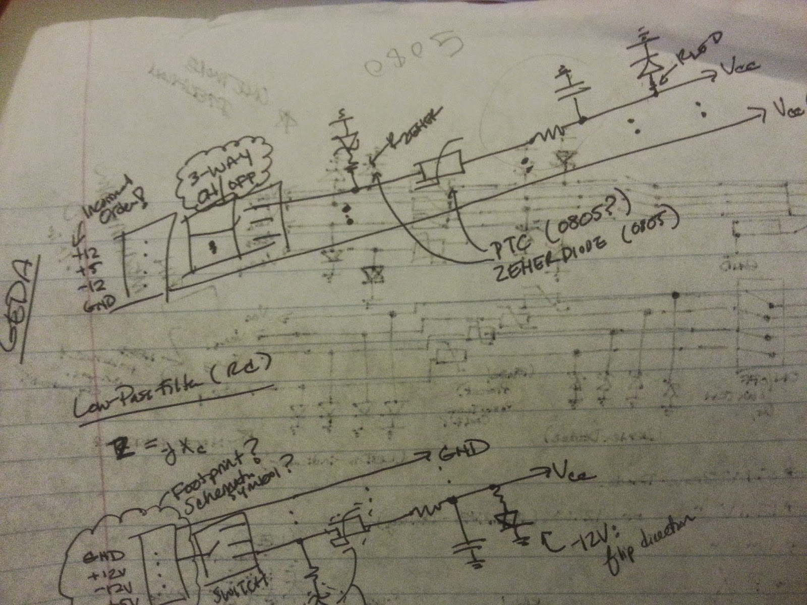
For Fall 2014, I decided to continue my work under Professor James Battat with the dark matter detector and he suggested doing so under PHYS250H -- an independent study in the Physics Department -- in order to receive credit for it. However, the project portion of the course veered from work with the PCB I created earlier and towards design of a PCB power supply for his Spring class PHYS310 "Experimental Physics." The power supply was needed for an Electronics student lab,  where a five-pin DIN draws in four voltage levels of +12V, -12V, +5V and GND for a solderless breadboard. The PCB I designed would use this connector to draw in the four voltage levels, filter for overcurrent and allow direct input into the rails of a solderless breadboard. At the beginning of the process, Battat and I create a concept diagram demonstrating the overall flow of the power supply and, from it, a rough circuit diagram was generated. Over time, the schematic changed with additional and...

Outlining the PCB

Image
Thursday, Dr. Phillips, Prof. Battat and I met from 10am to 3pm to focus on the design for the printed circuit board (PCB) to be used with the final prototype. We didn't even look at the gEDA software but, rather, discussed the needed components and their layout on the board itself. Once we found a room with a sufficient amount of white boards, the team dived into drawings and note-taking. Over the past few days, in debugging the breadboard circuitry, we have discussed greatly about the impact of impedance and capacity with long wires. We tried to eliminate such unnecessary distances with grouping families together, i.e. all the MUXes in parallel rows. We also looked into the issue of single-point grounding between digital and analog electronics. On the breadboard, the addition of a MUX to the same voltage supply greatly affected the abilities of the counter and could distort the counting completely. Additionally, we discovered that the MUX and 4-bit counter had ...

Hitting a Speed Bump

Image
With all the progress made last week with the counter, we still are having trouble seeing the correct Vout signal pattern of the MUX. Prof. Battat returned today and looked at the setup himself, and we made a few changes. Today was filled with lots of bumps and hills, and, at one point, we even thought we had burned out the counter and solder another just in case. In the book Moonwalking with Einstein , Foer states that humans sometimes reach a "plateau" where their progress or betterment at a task no longer increases. Nonetheless, he finishes by writing that one can overcome this stage by being extra-meticulous in their search for error. With 3 weeks left, it is time to be extra diligent in our work. The first change was to remove the 50 Ohm surface-mount, resistors on the MUX because it was affecting the counter's ability to count. Dr. Phillips and I were unsure how to address the issue earlier, but he suggested the use of buffers. The binary counter can drive 50 mA...

Return of the Gyroscope

Image
For the majority of this internship, I have neglected my second project with Larry in the machine shop, for which I has so much enthusiasm upon agreeing to do it. We have, however, been toying over how to go about creating this gyroscope between the original Youtube designs I found to a Solidworks homework design to a modified Solidworks file from a CAD community. We finally decided on the latter and modified the scale as well as the inner wheel, taking into account the stock we currently have in the shop and "reasonable" ranges for dimensions (see left). We quickly jumped into the project and, fortunately, I have experience on a few of the machines in the shop, which helped ease instructional time. Nonetheless, I did have to do a few exercises on a new machine: a (programmable) vertical mill with positioning edge, setting the center for the object I'm milling, etc. Larry wanted me to get comfortable with the machine first before using its programming features. In m...

Weekend Work: Practice Presentation I

Image
Today was the Plum Island Field Trip and the entire lab took the day off it seems. Yet, that doesn't mean we stop working on our practice presentations for tomorrow or anything else. Between the relaxation periods and the tutor training, I was able to finally email Mr. Knowles the part list for the gyroscope as I kept forgetting. I also finished up a first draft of the PowerPoint presentation (below): I tried to use the CRAP tool (Contrast, Repetition, Alignment, Proximity) in designing my presentation in addition to the advice from Professors Diesl and Conway from the workshop last week. I tried to make each slide as comprehensible in the simplest way possible and rely a lot more on speaker notes and discussion for explanation. First draft came out okay but there's always room for improvement.

End of the Third Week

Image
After a telephone conference between Prof. Battat, Dr. Phillips and I on Tuesday morning, I had a list of items to do and look into, (in addition to preparing my first presentation next week): Design a signal generator system to test multiplexer system (series of dividers) Design buffer amplifiers given a resistance of 50 Ω  and a load resistance of 2k Ω Read into the evaluation board manual for the Cyclone 5 FPGA (and prepare to program) I set off first to update my design of the multiplexer configuration with a 2-to-4 line decoder/demultiplexer as the logic system for SDs and a mod16 binary counter for the input lines (A0 and A1). We were about to go full circle on the counter system, back to the 4-input design I was working on, but this is absolutely simpler. In working on the signal generator system as a simulation of the 16-channel mux configuration, I started with a solderless breadboard to test different series of resistances with a battery pack. After t...

Celebration and a Little Disappointment

Image
4-Bit J-Input Logic Outline A Lovely Ice Cream Cake Happy Birthday to Me! Friday was filled with not only hard work but also a celebration. Right after the Science Center faculty lectures, my lab group surprised me with a chocolate-covered "Cookies and Cream" ice cream cake (and it was delicious) as well as lots of candy, limeade and a beautiful card. To say I was shocked would be an understatement. Now back to work! For the majority of the second week, I've been working on designing the 4x(4:1) multiplexer (mux) config and resolving issues in the switching between 16 channels by creating a 4-bit gray-code counter. On Friday, I was placing the last touches on the Logism simulation and checking if the output of the circuit matched that of the State Table, when Prof. Battat called me over. He showed me that he realized that we don't need a 4-Bit Gray Code Counter.... I had been working diligently for a whole week on a piece that we have ended up tossing aw...

Second Week II: The Gray Area

Image
4x(4:1) Mux Logic with Gray Code Breaking my blogging pattern, I'm writing about my work from today as I did quite a bit -- enough for one blog post. Following the last piece of writing, I corrected the logic table for the 4 x (4:1) to fit the specifications of our target multiplexer (mux)  LMH6574MA . However, after finishing it, I re-read Dr. Phillips's comments and noticed that, although the set-up diagram is great, it used binary code , meaning more than one input could change at a time and potentially generate a traffic jam with the break in signal patterns. Resultantly, we looked into utilizing gray code -- a digital code designed to allow only one bit (input) to change at a time -- to eliminate the possibility of multiple signal changes colliding into one another. 4x(4:1) Mux Logic with Binary Code Converting to gray code from binary wasn't too difficult and fortunately did not change most of my original design. I adapted the inputs to correlate with the gr...

Second Week: Highs and Lows

Image
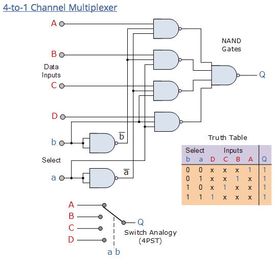
electronics-tutorials.ws/combination/comb_2.html On to the second week of work! I believe I have finally started to cross the line from a state of first-time jitters to what I call the "honeymoon stage" -- when all seems hopefully bright and I am in love with my project -- or what others may call the "calm before the storm." Today, I began my work day very early to make-up for the time I lost yesterday, as I was well under the weather. I caught up on all the emails I missed from Prof. Battat and Dr. Phillips, making a list of to-do's before our telephone conference at 10 am. Whereas, in the last meeting, I leaned a bit backwards to make sure I understood the flow of the conversation, I came prepared to engage in this conversation and walk away from the table with a clearer vision of my mission. We discussed: the decision to daisy-chain (string together) four 4:1 multiplexers (mux) to generate what was equivalent to a 16:1, leading us to buy the evaluation ...

An End to the First Week

Image
Since the last post, I have met with Prof. Battat several times to discuss current mini-goals and the overall framework for what we hope to be the end result. I have learned (most likely) over fifty different physics and electronics terms, read two papers on dark matter experimentation and lasted through a two-hour meeting between two very intelligent people on this particular project. I would call this a very successful first-week. For instance, yesterday, not only did I work more on the individual project and generate a Youtube playlist (below) of tutorials and lessons, I also gave a presentation on my progress through the week, had a group meeting to discuss the DRIFT experiment overall, and then jumped into a Python workshop. Today, I'll be busy again with an Alumnae lunch and a guest lecture in the afternoon on science education.  One day can pack in a whole lot.... On a similar note, two days ago, Prof. Battat and I met with Jim Phillips, who works at the Harva...

The First "Official" Day of Work

Image
Yesterday, I started the morning off with the Science Center breakfast-orientation session, followed by safety training, and then sat down with Prof. Battat to discuss the progress of my project and the guidelines for future tasks, as well as general logistics. Simply put, I need to prepare to dive into a whale of a job. We discussed my findings for analog-to-digital data converters and how to refine my searches into the google spreadsheet (also placed on the  project site under the research tab ). Furthermore, we began discussing the overall end goal for the circuit, breaking the design down into three possibilities. Detector Vacuum System The Ideal Design The ideal design is to connect the signal wires (SW) from the detector to several high-ratio multiplexers (Mux), i.e. 16:1, and form a Mux chip. Then that chip will be connected to possibly an octal (8) ADC chip that allows each SW to be processed at 1 MHz or higher. Finally, the chip will release a low-voltage differe...

Introducing... The Readout Electronics Project

Image
If you've followed my main blog and online engineering portfolio this far, then you know a little about me already. If not, I'm Christina Holman. I just finished my first year at Wellesley College and I loved every minute of it. Throughout the year, I pursued my potential dual-majors in Economics and Electrical Engineering. I explored my passion for engineering and interests in other STEM fields, from electricity and magnetism to engineering fundamentals to multivariable calculus. I even took my first course in economics and thoroughly enjoyed it. Thus far, the future looks quite bright. I was fortunate enough to hear of the  Science Center Summer Research Program  and the few research opportunities in physics. I was even more fortunate to be selected to work under Prof. James Battat with his ongoing investigation into dark matter. Although the project is under the label of "Physics," many of the skills and knowledge deals with engineering principles, so I canno...